This is a log entry about BB-88. See the project page to know more about it.
Now that the VGA RAMDAC has been removed from the VGA signal generation circuit, I need to find a way to output the correct levels for the red, green and blue outputs. The idea here is to get the same colors than the first 16 colors of the official VGA palette. These colors are very close to the CGA and base EGA palettes as well (with a grain of salt, see this article about the true color values of the CGA palette on int10h.org)
My goal is to get something close to what they describe as the canonical mapping, with intensity
levels of 0x00, 0x55, 0xAA and 0xFF.

Fortunately, the translation from a color index to the actual color is reasonably straightforward. Out of the 4-bit color value, bits 0, 1 and 2 each refer to blue, green and red; then bit 3 means "hi-intensity", for a lighter, brighter color. The brown color is a special case, but I'll get to it later.
Output signal
The full scale for VGA is from 0.0V for black to 0.7V output for full bright color channel, with a 75Ω termination inside the monitor.
Considering that 0xFF translates to 0.7V, we can assume that 0xAA is 0.47V and 0x55 is 0.23V. All that is left to do is to find a nice driver chip and figure out the right resistors combination that will result in the correct voltage being applied.
It's worth noting that the current resulting from sourcing 0.7V into 75Ω is close to 10mA1, which cannot be achieved with many LS or CMOS IC families. With this in mind, I've decided to use the 74AC244, an octal buffer with strong drivers, capable of more than 20mA per output, which should be plenty. The fact that it is actually split in two, with an Output Enable pin for each half is also a big advantage, as we'll see.
Output circuit
At first, I struggled a lot trying to find the correct combination of resistors, but it became way easier when I realized that instead of using the input value of 0V or 5V, I could also use the tri-state nature of the buffer's output. After some quick fiddling, I finally had something working in the simulator2.
The base for the output circuit of each channel would look like this (thus repeated three
times, for red, green and blue):
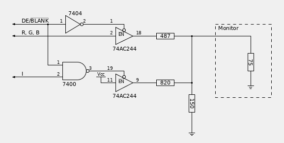
For the first half of the palette, where the Intensity bit is not set, only the 487Ω and 150Ω resistors are used. The resulting voltage going out into the monitor will be around 0.46V, very close to the intended level.
When the intensity bit is set, the 820Ω resistor comes into play and brings the signal up to
the desired 0.7V for full brightness, or to 0.26V when only the Intensity bit set, which is
close enough to the desired 0.23V.
When Intensity is not active, the buffer is disabled, leaving the 820Ω resistor floating,
having no effect at all.
Brown correction circuit
This is already very nice, but one color of that palette is not exactly the one we want: at
the moment, color 6 looks more like what's often called "olive", or "dark yellow", instead
of brown.

An additionnal circuit is thus needed to reduce the level of green for color 6, to get a more reddish tint. I did it with a resistor pulling the green signal down, activated by a 74AC139 selector.
Here is the adapted schematics for the green channel:
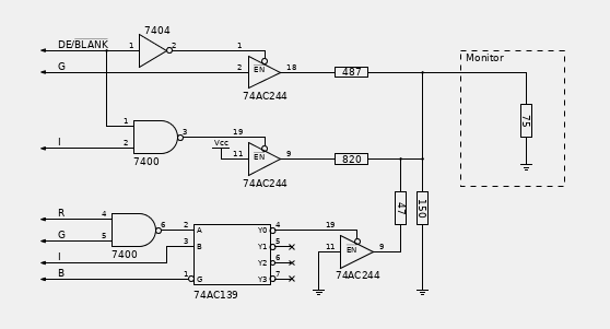
There is no need to check if we're currently in active display state here because we're just pulling to 0V anyway, so we can get away with half a 74AC139.
Actual result
I only had to wait a few days for the components to be delivered, and then, as is often the case, life got busy for several months. Until now...
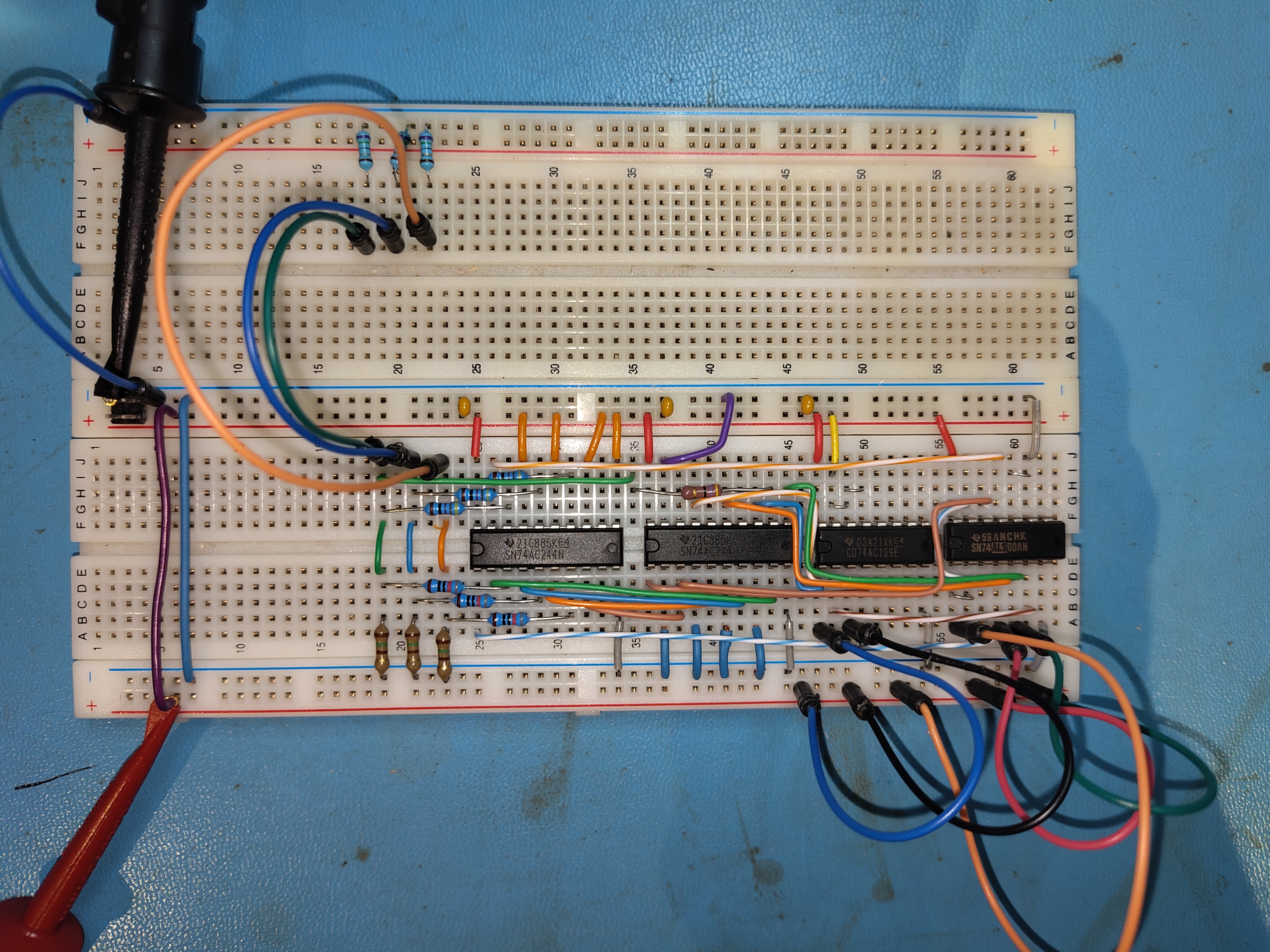
I first built the circuit on a separate breadboard, just to test with the multimeter that the outputs
acted as expected when I played with the inputs. It was also the opportunity to assign the physical slots
of the ICs to keep the connections short and simple. The layout looks promising, it should need only
minimal rework.
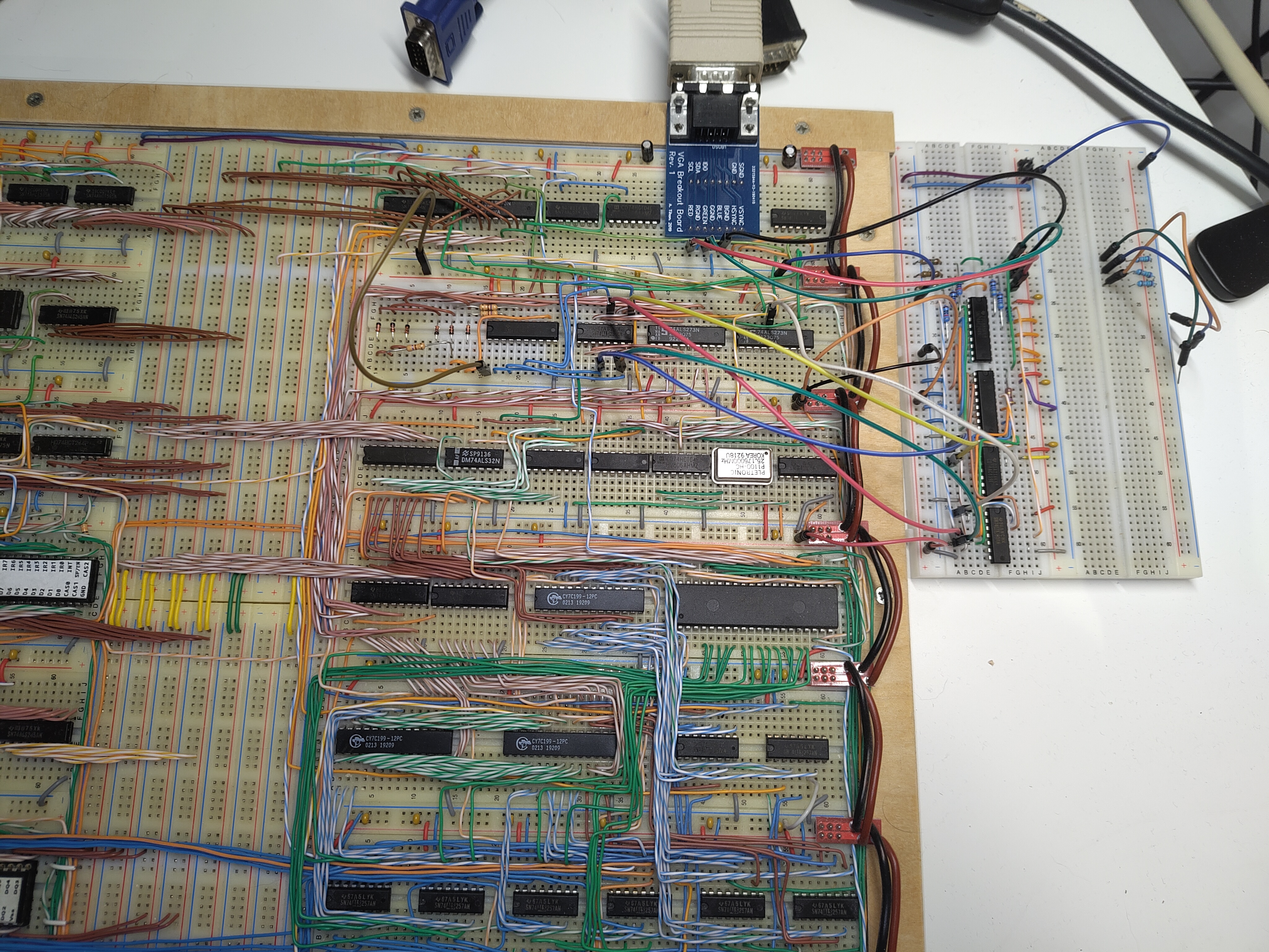
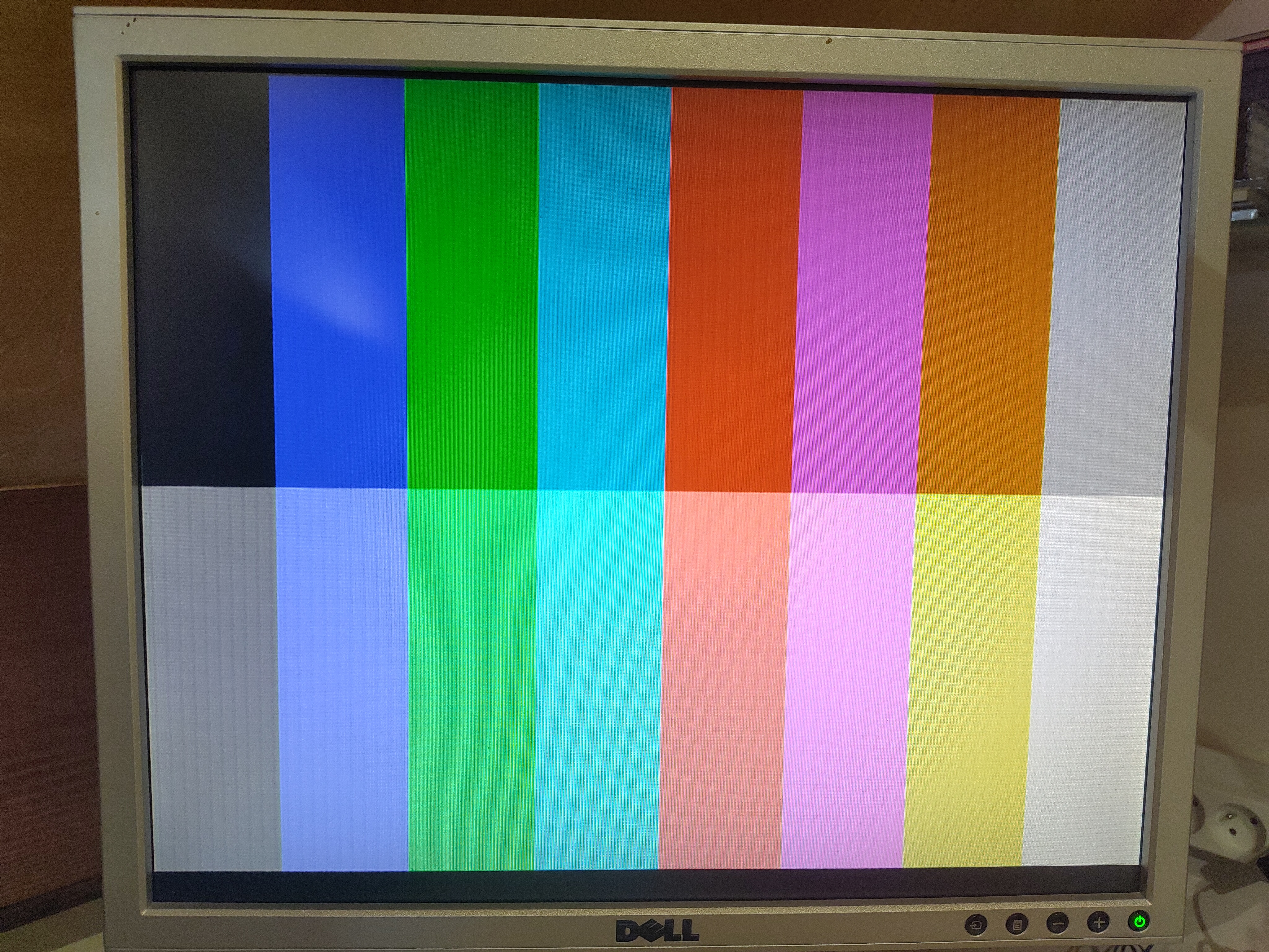
So, how does it perform? To test it in situation, I just put it next to BB-88's main circuit and connected
it with long wires, bypassing the crude temporary DAC.
The colors on the LCD are showing just as expected, although there is a slight vertical banding, mostly
in the bright colors.
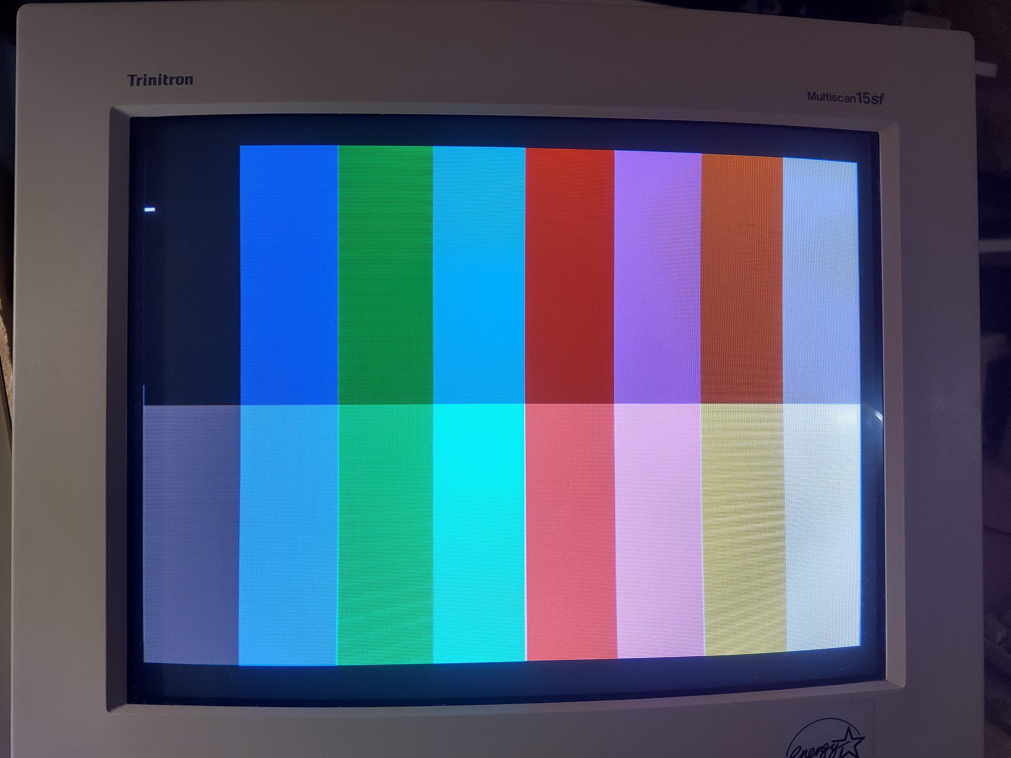
Here's a close-up view that better shows the banding:

On the other hand, the result on the CRT is excellent!
The text looks sharp, and there are no jailbars, no shadows and very little echo!
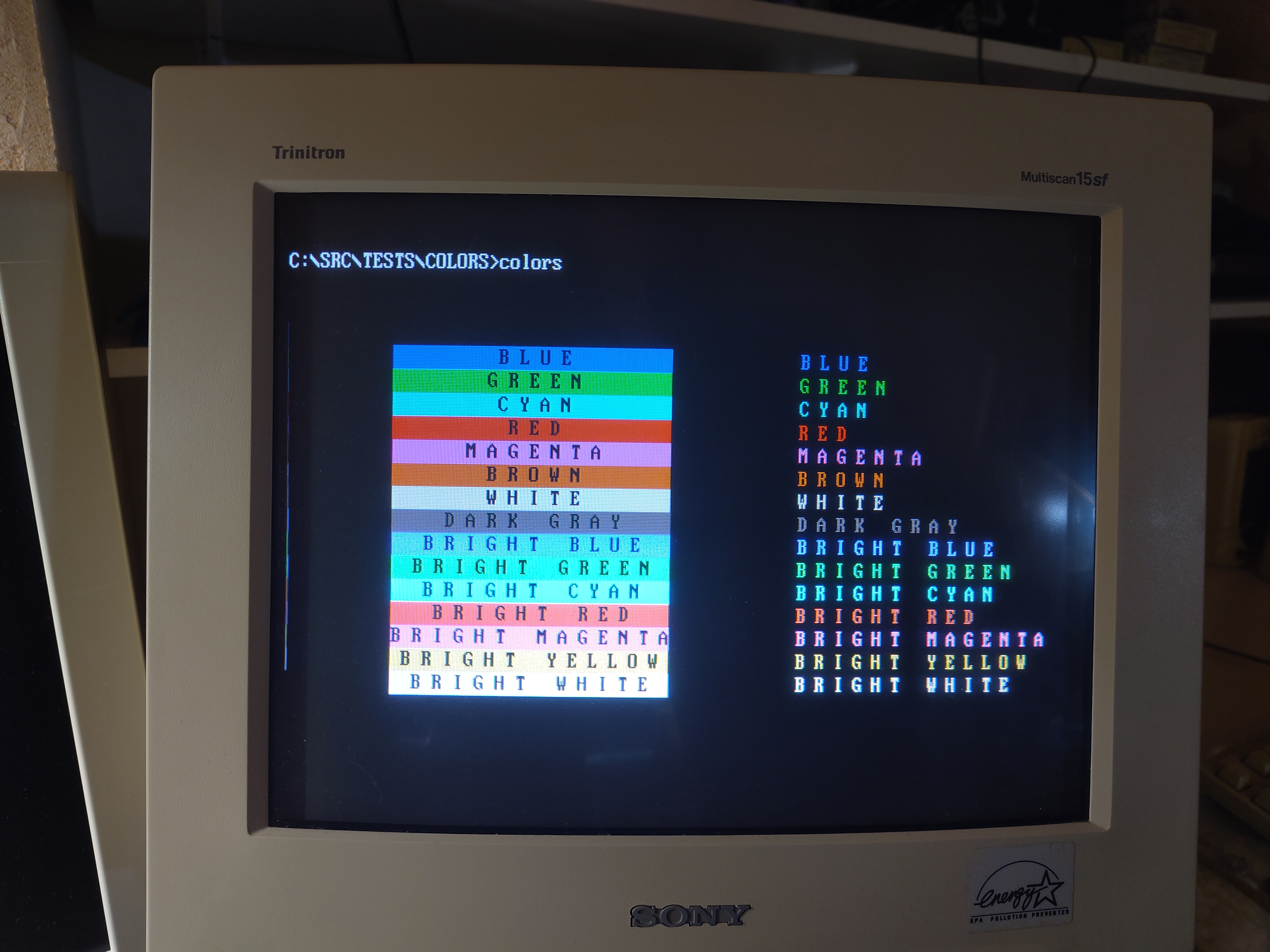
I'm super happy with the result!
That's how the circuit now looks like on the breadboard:
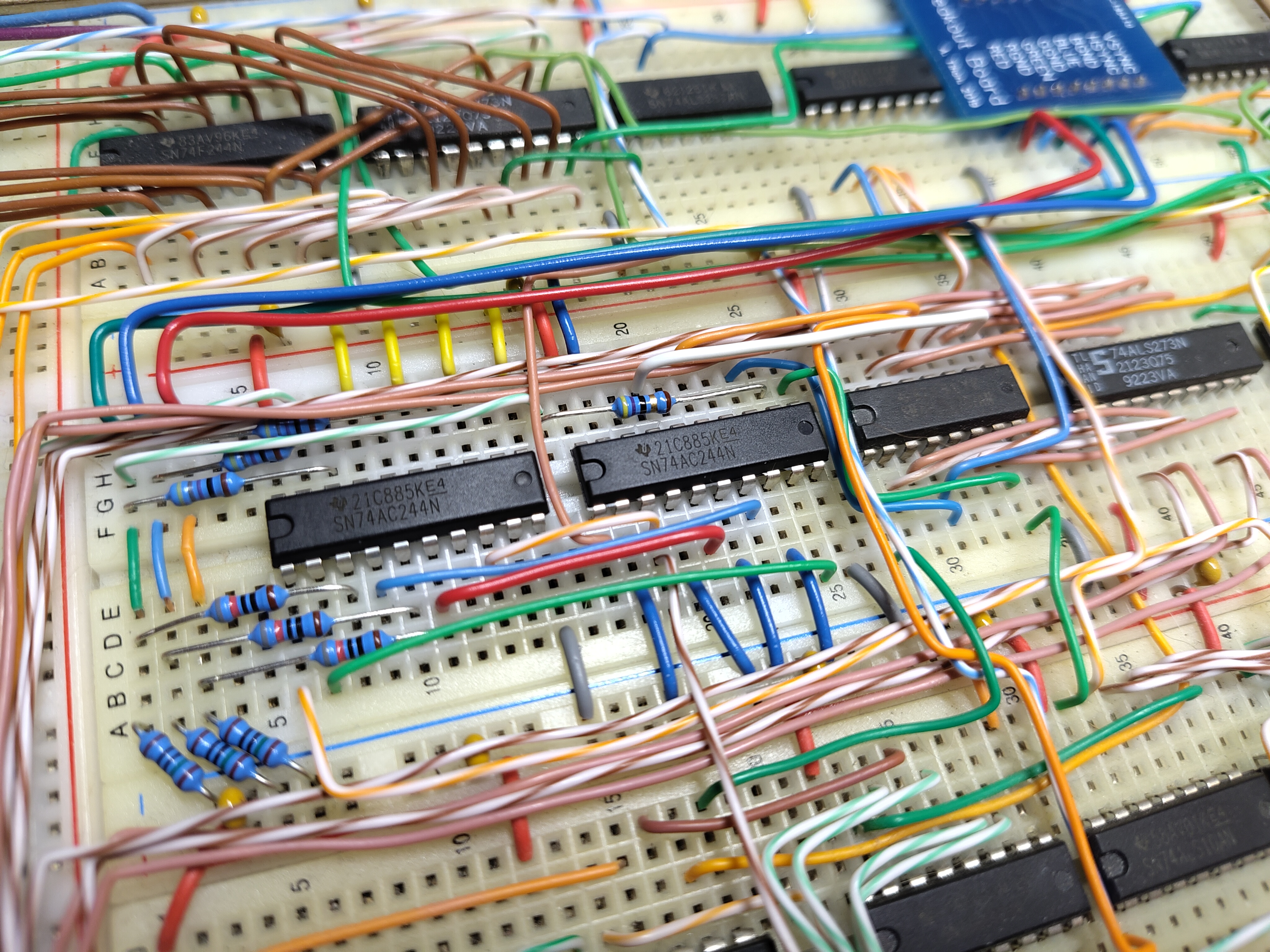
I had to be creative to squeeze it in the available space, by using (and sometimes abusing) free gates on various ICs already present in the build, but that was really worth it. Because that also means I won't have to remove the OPL2 section! And I just found out yesterday that you can find small DC-to-DC modules that convert a single 5V supply into a dual ±12V output, which is exactly what I'm missing since I replaced the ATX power supply with a Meanwell one!
Full schematic
I thought I'd publish the full schematic of the prototype output stage for reference (click the image for a
larger version), because I think it might be of use to anyone wanting to convert a 4-bit RGBI to analog VGA
levels:
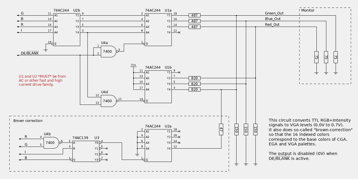
As you can see, the circuit as it is implemented also uses the remaining half 244 buffer to try
and get the timing slightly more consistent between the channels, but I reckon it shouldn't make
any visible difference in practice.
I also used one of the available NAND gates as an inverter in the prototype instead of adding another chip.
And yes, I'm aware that the output impedance does not match the monitor's input impedance, but that doesn't seem to be much of an issue.